This is the first post in a new series detailing the steps to build a digital stereo camera using the wildly popular Canon Ixus P&S cameras.
Most of you will have heard from CHDK which allows to use additional firmware functions in many Canon Powershot cameras. One flavour of CHDK, called SDM (Stereo Data Maker) was especially designed for stereo photography and allows for an almost perfect synch between cameras that are coupled using a USB based switch.
Since I already had one Canon Ixus 55 camera (named Powershot SD450 in the US), I wanted to use CHDK / SDM on it, but unfortunately at that time CHDK wasn't ported to the Ixus 55 yet. Well, it was a dirty job, but somebody had to do it, so I started to port CHDK to the Ixus myself and after many weeks and tremendous help I received from the CHDK forum, the Ixus 55 port was finally ready.
I then started to design a suitable USB switch to use with this camera but soon decided that I wanted to go for a more radical approach: Using CHDK / SDM out of the box ensures perfect synch but all the camera functions, especially the on/off switch as well as the zoom button had to be used independently on both cameras. Futhermore the use of an additional switch connected via USB to trigger the shutter seemed like a waste of space, because after all you already have a stereo camera with two perfectly designed shutter switches. Therefore the decision was clear: I wanted a hardwired camery where on/off switches, shutter- and zoom-buttons are coupled together with CHDK / SDM for perfect synch. I will describe how I built this camera in the next posts in this blog.
Dienstag, 13. Mai 2008
Samstag, 12. Januar 2008
Additional construction details of the 3D display
Since I was asked to post some more construction details here are some closeup-shots:
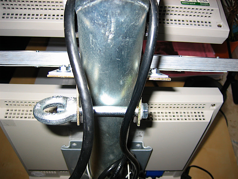
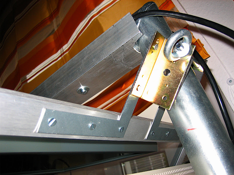
The displays are mounted using standard VESA wall mounts
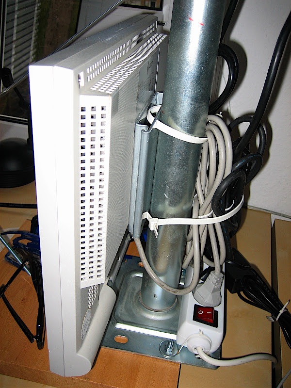
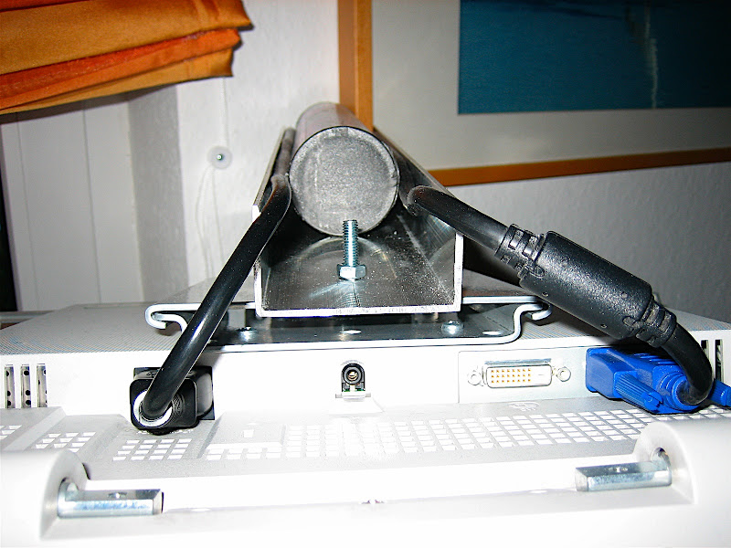
The top display was not mounted horizontally because I wanted to have a larger angle than 90 degrees to get a wider viewing angle:
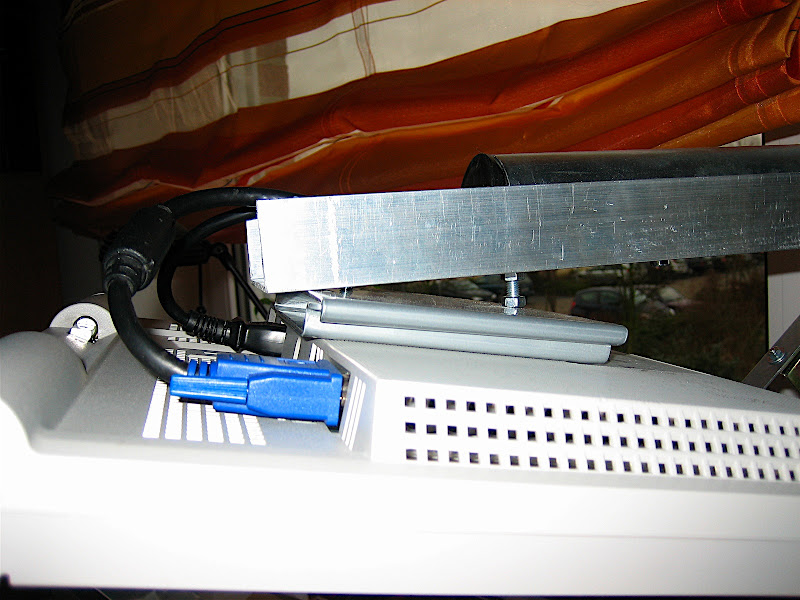
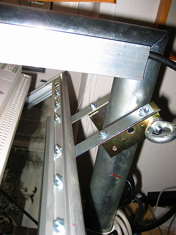
And finally the construction of the mirror frame:
The displays are mounted using standard VESA wall mounts


The top display was not mounted horizontally because I wanted to have a larger angle than 90 degrees to get a wider viewing angle:

And finally the construction of the mirror frame:


Donnerstag, 10. Januar 2008
Poor Man's Planar 3D Monitor
After shooting loads of pictures with my Fuji rig, I still had no posibility to view the resulting pictures in good quality. Therefore I decided to build a 3D monitor based on the Planar design.
My first attempt was to buy two 20" HP displays on Ebay with a fabulous resolution of 1600x1200. Unfortunately the polarization of these displays is unsuitable for the planar design, because it is horizontal or vertical and therefore the beamsplitter between the monitors is not able to change the direction of the polarization.


The initial test showed that the half-silvered mirror probably has a reflection/transmission ration of more than 50% because the transmitted picture was visibly weaker than the reflected one from the top monitor. However this could be easily compensated for by reducing the brightness of the top monitor correspondingly. An advantage of this situation is that ghosting resulting from reflection on the 2nd (non-coated) glass surface is not visible at all, because the brightness of the ghost reflection is much less compared to the primary reflection. This way I did not need to spend a fortune on a professional-grade beamsplitter with a anti-reflective coating on the backside.
So far I am absolutely happy with this setup.
My first attempt was to buy two 20" HP displays on Ebay with a fabulous resolution of 1600x1200. Unfortunately the polarization of these displays is unsuitable for the planar design, because it is horizontal or vertical and therefore the beamsplitter between the monitors is not able to change the direction of the polarization.
My 2nd attempt was to buy 2 cheap Eizo 15" screens which apparently have a 45 degree polarization and therefore seemed promising. To make the start easier, I decided to build this thing using a wall-mount for a satellite-dish as a basis. The screens itself were mounted using standard wall-mounts for LCD displays which I screwed into the steel satelite-dish holder. After a first serious measurement I found that I had to extend the upper arm quite a bit to be able to mount the beamsplitter in the bisecting angle. To this end I used a piece of standard aluminum profile that I had lying around (the same stuff I used to build the Fuji rig). The beamsplitter was made of half-silvered mirror that I was able to get from a local glass&mirror shop. I connected it to the monitor-stand using an aluminum picture frame and some standard parts from a DIY shop. And finally, this is the end result (in side-by-side stereo, of course ;-):
The initial test showed that the half-silvered mirror probably has a reflection/transmission ration of more than 50% because the transmitted picture was visibly weaker than the reflected one from the top monitor. However this could be easily compensated for by reducing the brightness of the top monitor correspondingly. An advantage of this situation is that ghosting resulting from reflection on the 2nd (non-coated) glass surface is not visible at all, because the brightness of the ghost reflection is much less compared to the primary reflection. This way I did not need to spend a fortune on a professional-grade beamsplitter with a anti-reflective coating on the backside.
So far I am absolutely happy with this setup.
Sonntag, 28. Oktober 2007
First Light ;-)
Here are the first results from a short walk this morning:


And here is a video that demonstrates how the camera operates:
And here is a video that demonstrates how the camera operates:
Measuring Synch
The easiest way to measure the synchronization of the cameras involved using my turntable with a corresponding scale:


Setting the turntable to 45rmp means that a deviation of 10 degrees corresponds to a time-difference of 0,037 seconds.
Here is the first test shot:


The time-difference is aproximately 0,015 seconds although the second camera has received some flash from the first.
What you also see is a significant deviation in the vertical direction, which means I have to adjust the rig accordingly. Time to work on the next post ... ;-)
Setting the turntable to 45rmp means that a deviation of 10 degrees corresponds to a time-difference of 0,037 seconds.
Here is the first test shot:
The time-difference is aproximately 0,015 seconds although the second camera has received some flash from the first.
What you also see is a significant deviation in the vertical direction, which means I have to adjust the rig accordingly. Time to work on the next post ... ;-)
Samstag, 27. Oktober 2007
Dismantling and Wiring the cameras
To allow for a good synchronization it is necessary to switch on the cameras exactly in parallel, therefore not only the shutter switch but also the on/off switch needs to be connected. In this project I did not couple the zoom switches as well, because the soldering points looked to delicate. I might try this in the future, though ...
Dismantling the cameras is pretty straighforward: You'll only need a size-0 Philips screwdriver. After unscrewing all three visible screws on the outside case:


You are then able to carefully pull of the back-case:

Be careful not to touch the solder-contacts between the LC-display and the micro-buttons on the right upper side as some of them lead to the flash-capacitor. If you touch this area you can get a severe shock! During my first investigation of this camera, I accidentally connected two of the contacts while measuring, which resulted in a small explosion and the need to buy another camera from Ebay. Apparently I destroyed the mainboard completely! If you want to be sure, you can discharge the capacitor using a corresponding resistor. But since we are only working with the shutter-board this is not a must. BTW a good description of the procedure to dismantle the camera can be found here.
To couple the cameras we need to solder some wires to the shutter-board which is connected to the mainboard via a flex-cable that can be disconnected after unlocking one of the connoctors:

Before you are able to reach the shutter-board, you need to pull-out the mainboard with the optical-unit. To this end you need to unscrew the screw below the LC-display. The LC-display can be disconnected after unlocking the flex-cable connector. After that you can carefully pull-out the whole assembly.

Now you can disconnect the shutter board. The interesting contacts are shown in the next picture:

I decided to use a direct connection between both cameras. An easy way to route the wires out of the camera was to use the hole for the power-connector which I did not plan to use anyway, because I have a stand-alone charger for my batteries. This meant that I had to unsolder the power-socket first:


I then prepared a flat-flex cable with 5 leads (2 for power-switch, 3 for focus, shutter and common ground) and routed this though the back-cases:

The easiest way to route the cable within the camera appeared to be as follows:

The soldering requires a small soldering-tip and fairly shake-free hands but if I can do it (being a theoretical(!) physicist by education), then anybody can do it ;-)
I did not use the common-ground on the shutter-board, but found that one of the contacts for the battery socket that I had removed was also connected to ground, so I used that one and therefore needed only to route 4 wires completely through the camera to the shutter-board.
After re-assembling the camera and performing a simple test, the camera did not power-up. After several frustated minutes I found out the reason: The battery-connector that I removed also provided a connection between two soldering-pads that now, of course, was missing. My initial inspection suggested that one of the pads was not connected to anything, so I didn't care but apparently I was wrong. I solved the problem by adding an additional wire-bridge to this contact:

Now the camera started to work as usual and so I reassembled it. I now did exactly the same with the second camera and after reassembling everything and mounting both cameras on the rig this is the final result:

First test shots looked good. Hoepfully I will start the first serious testing tomorrow.
Dismantling the cameras is pretty straighforward: You'll only need a size-0 Philips screwdriver. After unscrewing all three visible screws on the outside case:
You are then able to carefully pull of the back-case:
Be careful not to touch the solder-contacts between the LC-display and the micro-buttons on the right upper side as some of them lead to the flash-capacitor. If you touch this area you can get a severe shock! During my first investigation of this camera, I accidentally connected two of the contacts while measuring, which resulted in a small explosion and the need to buy another camera from Ebay. Apparently I destroyed the mainboard completely! If you want to be sure, you can discharge the capacitor using a corresponding resistor. But since we are only working with the shutter-board this is not a must. BTW a good description of the procedure to dismantle the camera can be found here.
To couple the cameras we need to solder some wires to the shutter-board which is connected to the mainboard via a flex-cable that can be disconnected after unlocking one of the connoctors:
Before you are able to reach the shutter-board, you need to pull-out the mainboard with the optical-unit. To this end you need to unscrew the screw below the LC-display. The LC-display can be disconnected after unlocking the flex-cable connector. After that you can carefully pull-out the whole assembly.
Now you can disconnect the shutter board. The interesting contacts are shown in the next picture:
I decided to use a direct connection between both cameras. An easy way to route the wires out of the camera was to use the hole for the power-connector which I did not plan to use anyway, because I have a stand-alone charger for my batteries. This meant that I had to unsolder the power-socket first:
I then prepared a flat-flex cable with 5 leads (2 for power-switch, 3 for focus, shutter and common ground) and routed this though the back-cases:
The easiest way to route the cable within the camera appeared to be as follows:
The soldering requires a small soldering-tip and fairly shake-free hands but if I can do it (being a theoretical(!) physicist by education), then anybody can do it ;-)
I did not use the common-ground on the shutter-board, but found that one of the contacts for the battery socket that I had removed was also connected to ground, so I used that one and therefore needed only to route 4 wires completely through the camera to the shutter-board.
After re-assembling the camera and performing a simple test, the camera did not power-up. After several frustated minutes I found out the reason: The battery-connector that I removed also provided a connection between two soldering-pads that now, of course, was missing. My initial inspection suggested that one of the pads was not connected to anything, so I didn't care but apparently I was wrong. I solved the problem by adding an additional wire-bridge to this contact:
Now the camera started to work as usual and so I reassembled it. I now did exactly the same with the second camera and after reassembling everything and mounting both cameras on the rig this is the final result:
First test shots looked good. Hoepfully I will start the first serious testing tomorrow.
Construction of the Aluminum Rig
The rig was made of standard aluminium U-Profile (forgive me if that is not the correct technical term in english). As a counterexample to Murphys Law I was able to find it with almost exactly the right size to accomodate two cameras.

After measuring the size of the cameras I came up with the following diagram:

Using a standard jigsaw I then ended up with the following rig:

To be able to attach the camera with a variable stereo-base, I needed slot-holes. Having only a drill and rasps this turned out to be a rather tedious job, but after 2 hours the result looked okay:

Finally using two standard camera screws, the rig was finished.

After measuring the size of the cameras I came up with the following diagram:
Using a standard jigsaw I then ended up with the following rig:
To be able to attach the camera with a variable stereo-base, I needed slot-holes. Having only a drill and rasps this turned out to be a rather tedious job, but after 2 hours the result looked okay:
Finally using two standard camera screws, the rig was finished.
Abonnieren
Posts (Atom)