To allow for a good synchronization it is necessary to switch on the cameras exactly in parallel, therefore not only the shutter switch but also the on/off switch needs to be connected. In this project I did not couple the zoom switches as well, because the soldering points looked to delicate. I might try this in the future, though ...
Dismantling the cameras is pretty straighforward: You'll only need a size-0 Philips screwdriver. After unscrewing all three visible screws on the outside case:
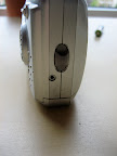
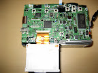
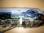
You are then able to carefully pull of the back-case:
Be careful not to touch the solder-contacts between the LC-display and the micro-buttons on the right upper side as some of them lead to the flash-capacitor. If you touch this area you can get a severe shock! During my first investigation of this camera, I accidentally connected two of the contacts while measuring, which resulted in a small explosion and the need to buy another camera from Ebay. Apparently I destroyed the mainboard completely! If you want to be sure, you can discharge the capacitor using a corresponding resistor. But since we are only working with the shutter-board this is not a must. BTW a good description of the procedure to dismantle the camera can be found
here.
To couple the cameras we need to solder some wires to the shutter-board which is connected to the mainboard via a flex-cable that can be disconnected after unlocking one of the connoctors:
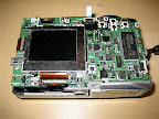
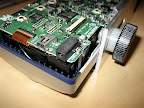
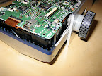
Before you are able to reach the shutter-board, you need to pull-out the mainboard with the optical-unit. To this end you need to unscrew the screw below the LC-display. The LC-display can be disconnected after unlocking the flex-cable connector. After that you can carefully pull-out the whole assembly.
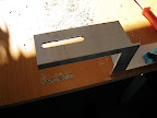
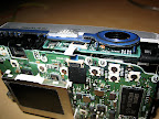
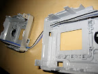
Now you can disconnect the shutter board. The interesting contacts are shown in the next picture:

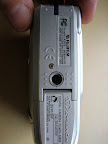
I decided to use a direct connection between both cameras. An easy way to route the wires out of the camera was to use the hole for the power-connector which I did not plan to use anyway, because I have a stand-alone charger for my batteries. This meant that I had to unsolder the power-socket first:
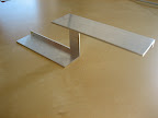
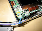
I then prepared a flat-flex cable with 5 leads (2 for power-switch, 3 for focus, shutter and common ground) and routed this though the back-cases:
The easiest way to route the cable within the camera appeared to be as follows:
The soldering requires a small soldering-tip and fairly shake-free hands but if I can do it (being a theoretical(!) physicist by education), then anybody can do it ;-)
I did not use the common-ground on the shutter-board, but found that one of the contacts for the battery socket that I had removed was also connected to ground, so I used that one and therefore needed only to route 4 wires completely through the camera to the shutter-board.
After re-assembling the camera and performing a simple test, the camera did not power-up. After several frustated minutes I found out the reason: The battery-connector that I removed also provided a connection between two soldering-pads that now, of course, was missing. My initial inspection suggested that one of the pads was not connected to anything, so I didn't care but apparently I was wrong. I solved the problem by adding an additional wire-bridge to this contact:
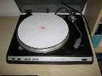
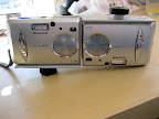
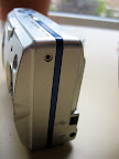
Now the camera started to work as usual and so I reassembled it. I now did exactly the same with the second camera and after reassembling everything and mounting both cameras on the rig this is the final result:
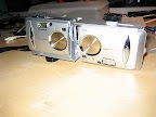
First test shots looked good. Hoepfully I will start the first serious testing tomorrow.