Sonntag, 15. Juni 2008

Additional Pictures and a Video of the Final Ixus 55 Rig

After a few weeks of optimizing some of the construction details here are some pictures of the final stereo camera:


Between the cameras strong magnets provide stability:


When the rig is folded the total size is just 10x7x4,5 cm (W*H*D), which means it fits in a very small camera bag:


The cable to connect both cameras can be routed within the hinge mechanism behind the magnets:


The cable was made from a standard USB cable and selfmade plugs with a housing made of epoxy:


Here you can see the socket within the camera:


The following video demonstrates that he camera can be controlled like a true point-n-shoot camera:


Mittwoch, 14. Mai 2008

3D Digital Stereo Ixus 55 (Part 4: The Software)

As already mentioned in the introduction, I wanted to use CHDK or SDM on this camera but without having to use an external switch connected via USB. To achieve this I studied the source code of SDM carefully (Thanks David for making it public!) and rewrote the internal synch routine as follows and added it to the standard Allbest CHDK branch:

void wait_until_remote_button_is_released(void)
{
asm volatile ("STMFD SP!, {R0-R11,LR}\n"); // store R0-R11 and LR in stack

#define DELAY_TIMEOUT 10000
#define KBD_MASK 0x4
int tick;
long z, *x;

debug_led(1);
_kbd_pwr_on();
tick=get_tick_count();

do {
z = physw_status[2] & KBD_MASK;
x = (void*)0xc0220208;
_kbd_read_keys_r2(physw_status);

}
while( (!z) && ((int)get_tick_count()-tick < DELAY_TIMEOUT));

_kbd_pwr_off();

debug_led(0);
if (fd>=0) close (fd);

asm volatile ("LDMFD SP!, {R0-R11,LR}\n");
}


This way, the cameras do not wait for the external USB switch to be released but the shutter fires after the nomal shutter switch has been released. The shoot sequence therefore is pretty straightforward:
1. Half press the shutter to focus
2. Full press the shutter until both blue LEDs light up
3. Release the shutter and a highly synchronized pair of pictures is taken.

I havent measured the synch systematically yet because I don't have a CRT monitor anymore to be able to use the Camera Synch Tester.

3D Digital Stereo Ixus 55 (Part 3: Building the Rig)

The original idea was to make a stereo camera that can be used more or less like an ordinary point and shoot camera. An important goal therefore was to design a rig that does not add unnecessary size and weight to the cameras. Using ready-made parts from a local DIY-shop I build the following rig:

The cameras are then attached using standard 1/4" screws:


Did I forget something important???

Oh yes ;-) one of the standard parts from the DIY-shop was small hinge, so you can fold the rig and the camera will fit nicely into a small camera bag:


To ensure that the rig is stable when unfolded, I used some small magnets which are place within the hinge as you can see on the following picture:

The magnets are not actually glued in yet, because the current rig is still a prototype where the vertical alignment of the cameras is not good enough yet. Since the price of the two angles and the hinge is just a little more than 1 Euro I bought some more parts to be able to experiment a little ...

So this is the current design when everything is completely assembled:

Dienstag, 13. Mai 2008

3D Digital Stereo Ixus 55 (Part 2: Hardwiring the cameras)

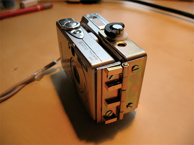
The first task was relatively easy: Open up the camera by removing the 6 tiny screws (use a size-0 Philips screwdriver for this, other cameras might even require size 00 and be prepared that you might need to apply some force. Be sure to use a screwdriver of the correct size to avoid that the heads get damaged) and remove the front and back housing. The plate connecting the switches can then be easily removed and the switch board can be seen. After using a multimeter to measure the contacts on this board, I obtained the following diagram:


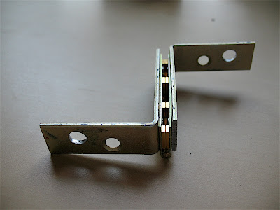
The next step was by far the most difficult: How to connect the switches of two tiny little cameras without damaging too much and without using a direct cable connection that would prevent the cameras from being usable alone? After researching many different connector designs I ended up with multipin- and multipoint connectors having a 1,27mm grid:

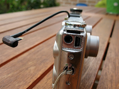
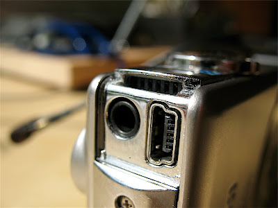
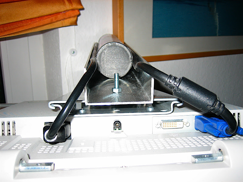
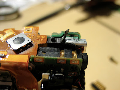
The only place to put the connector is directly above the usb and video socket where normally the rubber socket-cover is connected to the housing. This is the only part we need to get rid of. First we have to remove the small plastic pin that holds the rubber cover in place using a sharp knife:

Afterwards you can see that the connector (after being shortened to 7 pins) would fit nicely into the resulting space:

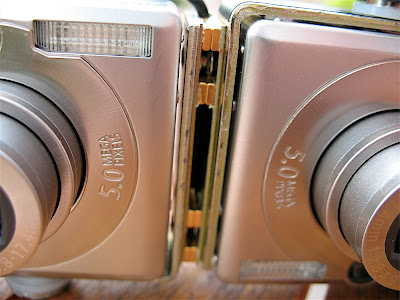
Most important thing however is that this connector can be reached from the outside simply by plugging a 7-pin multipin connector into the slot where the rubber cover used to be.

We now must make a little more additonal space inside above the USB and video ports: Remove the top 1mm of the plastic part between both ports:

After shortening two of the seven pins of the connector and making it just a little slender using a rasp, it fits nicely into the resulting space and should be glued there using a tiny portion of superglue:


Now the even more delicate work begins: For the internal wiring I used leads from a 100pin ide cable which is relatively thin, not too flexible and easy to solder. It is very important to customize the cables before soldering:


The soldering itself is quite delicate and requires a fairly shake-free hand but is not too difficult. As you can see in the following picture: I am definitely NOT a professional is this discipline ;-))


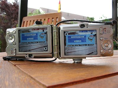
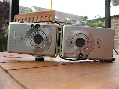
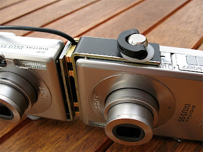
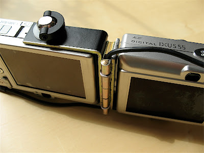
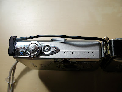
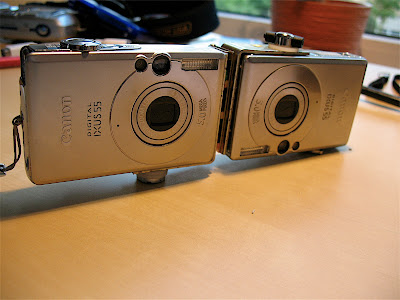
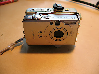
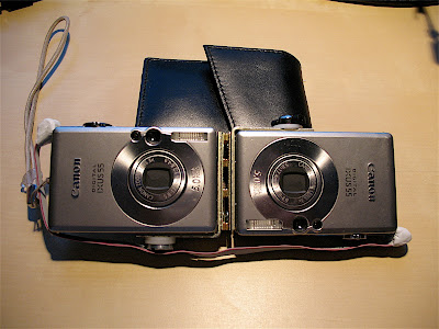
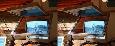
After reassembling the cameras the only visible difference is the missing cover:


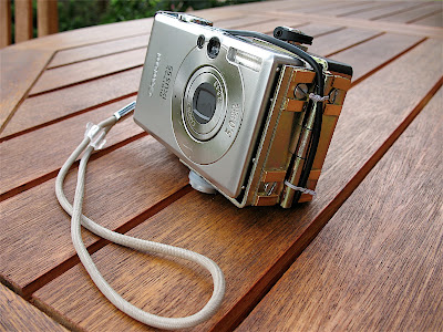
A suitable cable to connect the cameras was soldered using multipin connectors and an old flexible IDE cable. The plugs were made using 2-component epoxy. Not a pretty design but the cable does work ;-)

After a few weeks I found out that the camera behaved strangely when the battery in one of the cameras was running low. I fixed that by cutting one of the connections between the cameras that connected the side of the on-off switch that was directly connected to the batteries. So actually you only need a 6-pin connection between the cameras.

3D Digital Stereo Ixus 55 (Part 1: Introduction)

This is the first post in a new series detailing the steps to build a digital stereo camera using the wildly popular Canon Ixus P&S cameras.

Most of you will have heard from CHDK which allows to use additional firmware functions in many Canon Powershot cameras. One flavour of CHDK, called SDM (Stereo Data Maker) was especially designed for stereo photography and allows for an almost perfect synch between cameras that are coupled using a USB based switch.

Since I already had one Canon Ixus 55 camera (named Powershot SD450 in the US), I wanted to use CHDK / SDM on it, but unfortunately at that time CHDK wasn't ported to the Ixus 55 yet. Well, it was a dirty job, but somebody had to do it, so I started to port CHDK to the Ixus myself and after many weeks and tremendous help I received from the CHDK forum, the Ixus 55 port was finally ready.

I then started to design a suitable USB switch to use with this camera but soon decided that I wanted to go for a more radical approach: Using CHDK / SDM out of the box ensures perfect synch but all the camera functions, especially the on/off switch as well as the zoom button had to be used independently on both cameras. Futhermore the use of an additional switch connected via USB to trigger the shutter seemed like a waste of space, because after all you already have a stereo camera with two perfectly designed shutter switches. Therefore the decision was clear: I wanted a hardwired camery where on/off switches, shutter- and zoom-buttons are coupled together with CHDK / SDM for perfect synch. I will describe how I built this camera in the next posts in this blog.

Samstag, 12. Januar 2008

Additional construction details of the 3D display

Since I was asked to post some more construction details here are some closeup-shots:

The displays are mounted using standard VESA wall mounts


The top display was not mounted horizontally because I wanted to have a larger angle than 90 degrees to get a wider viewing angle:


And finally the construction of the mirror frame:


Donnerstag, 10. Januar 2008

Poor Man's Planar 3D Monitor

After shooting loads of pictures with my Fuji rig, I still had no posibility to view the resulting pictures in good quality. Therefore I decided to build a 3D monitor based on the Planar design.
My first attempt was to buy two 20" HP displays on Ebay with a fabulous resolution of 1600x1200. Unfortunately the polarization of these displays is unsuitable for the planar design, because it is horizontal or vertical and therefore the beamsplitter between the monitors is not able to change the direction of the polarization.


My 2nd attempt was to buy 2 cheap Eizo 15" screens which apparently have a 45 degree polarization and therefore seemed promising. To make the start easier, I decided to build this thing using a wall-mount for a satellite-dish as a basis. The screens itself were mounted using standard wall-mounts for LCD displays which I screwed into the steel satelite-dish holder. After a first serious measurement I found that I had to extend the upper arm quite a bit to be able to mount the beamsplitter in the bisecting angle.  To this end I used a piece of standard aluminum profile that I had lying around (the same stuff I used to build the Fuji rig). The beamsplitter was made of half-silvered mirror that I was able to get from a local glass&mirror shop.  I connected it to the monitor-stand using an aluminum picture frame and some standard parts from a DIY shop. And finally, this is the end result (in side-by-side stereo, of course ;-):


The initial test showed that the half-silvered mirror probably has a reflection/transmission ration of more than 50% because the transmitted picture was visibly weaker than the reflected one from the top monitor. However this could be easily compensated for by reducing the brightness of the top monitor correspondingly. An advantage of this situation is that ghosting resulting from reflection on the 2nd (non-coated) glass surface is not visible at all, because the brightness of the ghost reflection is much less compared to the primary reflection. This way I did not need to spend a fortune on a professional-grade beamsplitter with a anti-reflective coating on the backside.

So far I am absolutely happy with this setup.