Sonntag, 24. April 2011

Sync-Test of Kodak ZX1-Rig: Negative Results so far

Yesterday evening I made a few measurements of the resulting sync of the videos. The following test-sequence was made using 720p and 30 pics/sec:
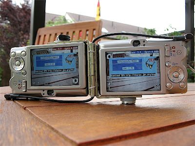
  • Switch on cameras synchronously via USB remote
  • Start video recording on both cameras
  • Fire a flashlight (thanks Matthias for this great tip!)
  • Stop video recording on both cameras
  • Shutdown cameras
This sequence was repeated about 10 times and the resulting video-pairs were uploaded into the StereoMovieMaker. The video-pairs were then adjusted for frame-accuracy (this was still necessary because the start of the recording was done using the buttons on each camera) and the first frame that shows the flash was observed in detail.

Due to the rolling shutter, the flash manifests itself as a white area that starts at a specific line in the frame. In theory, with perfectly synchronized cameras, the lines where the flash starts would be identical in this frame and the resulting sync-error would be less than 46 microseconds (again, thanks Matthias for the explanation!).

What I observe for the ZX1-Pair is, unfortunately, a completely different behaviour: The lines where the flash starts differ quite randomly between about 100 lines and half a frame. This means that the cameras are in fact still completely unsynchronized.

A possible explanation for this behaviour could be that camera performs some additional steps during startup before the actual video-oszillator circuit starts and these additional steps are dependent on each camera and somehow random. For Sony Cameras and a LANC-remote the start of the cameras using LANC immediately starts the oszillator and the cameras (usually) start in perfect sync and then slowly drift apart later.

Maybe somebody has additional suggestions what went wrong here, but based on these results the USB-remote is completely useless and it would be sufficient to switch on each camera separately.

It would be very interesting to repeat this test with camcorders of other brands: If a camcorder starts automatically when connected via USB to a PC and you happen to own two of these cameras and a simple USB-hub then try the following:
  • Connect both camera via USB to the USB-hub
  • Connect the hub to a PC until the cameras boot
  • Start video recording on both cameras
  • Fire a flashlight
  • Stop video recording
  • Check the sync of the resulting video pair in StereoMovieMaker
If we find a cheap HD camera that delivers synched videos in this test, we have the perfect low-cost 3d action cam ;-)


Samstag, 23. April 2011

Poor Man's LANC for Kodak ZX1?

After more than two years (and countless photos using my Ixus 55 Stereo-Rig) I stumbled over a real bargain for Kodak ZX1 camcorders: A german online-shop sold them for 49,- EUR. I decided to order two of them to check if they can be used for HD stereo videos. Apparently this is by no means a new idea: Several people have successfully used these camcorders for 3D-Stereo especially because this model offers a 1280x720 resolution at 60p, so that the maximal sync-error between frames is not larger than 8ms.

For 3d Stereo-Vids having perfect sync is very important to avoid eye-strain in scenes with a lot of movement. For the more expensive Soncy-camcorders a very good stereo solution based on the LANC-protocol exists. Here a suitable remote control can switch on both camcorders at exactly the same time so that their internal oszillators start in perfect sync. Using LANC it is even possible to measure the deviation between the oszillators so that you can see when the cameras begin to drift apart slowly.

For the low-cost Kodak ZX1 there is no such thing as a LANC-port, but the Kodak has a micro-USB port that might serve a similar purpose. When I plugged the USB-cable into the camera, I noticed that it automatically turned on. Apparently the camera is sensitive to the 5v USB voltage that is provided by the USB-host. I still had various electronics parts lying around from my experiments with Canon CHDK/SDM and decided to construct a remote control that would switch on both cameras in sync.

First of all I had to work on the USB-cables. Unfortunately the Kodak uses a non-standard 8-pin micro usb-plug so I had to use the original cables provided with the camera. Using a sharp knife, I removed all the plastic and ended up with the following small plug:


I then used the most simple electric circuit possible to power the micro usb with a 3,6V lithium battery and a push-button:


Pressing the button provides 3.6V to the corresponding USB-contacts. So I ended up with the following Stereo-Rig:


I still need to work on the second plug, but this should be sufficient for testing purposes. So how does this work:
A short press on the yellow push-button powers on both cameras in sync. Bingo. Even better, when I press it a little longer, the camera switches off again. I have no idea why the camera does that but apparently I created a real on/off switch by accident, nice. ;-)

To start and stop recording you still have to use the buttons on the camcorder, but since you have to edit the video clips afterwards anyway this is only a minor inconvenience. As a workaround I could buy a IR-remote for this purpose but the IR-receiver is located on top of the camera so it is not really more convenient to start recordings this way.

The next step will be to test the sync of the resulting videos and in particular to compare the sync with the standard method of switching on both cameras separately. Stay tuned ... ;-)

Samstag, 4. April 2009

Additional details of the hinge-mechanism

Since I received several requests regarding the construction of the rig, here are some additional information and pictures to explain the construction. You'll need the following parts: 
  • 2 Metal Brackets (I used a standard size of 70mm length and 16mm width)
  • 1 Metal Hinge (Length 51mm, with 12mm, total width 30mm when unfolded)
  • 8 small magnets (10x4 mm, with a thickness of 1mm) 
The Metal parts should be fairly standard parts that you can get from any DIY shop. I purchased the magnets from a german online-shop.
Before you begin the construction, you must first measure the exact distance (d) from the tripod-socket of the camera to the middle of the lens. For the Ixus 55 d=27mm. If you double this distance you get the total distance (2d=54mm) that the two bottom-sides of the brackets must have to ensure that the camera lenses are on the same height.
The second measurement you need is the distance between the left side of camera and the middle of the tripod socket (s=28mm in case of the Ixus 55), because you have to drill corresponding holes into the brackets later to mount the cameras. The following picture explains this hopefully a bit better:

Von Fotoarchiv


First step then is to shorten the metal brackets to the size you need using a saw. The side of the bracket that will be connected to the hinge should be roughly equal to 2d, which should of course roughly match the lenght of the hinge you purchase. The other side of the brackets should be long enough to support the cameras firmly. In the case of the Ixus 55, 40mm turned out to be the optimal size, because this will provide enough stability but also lets you access the battery chamber when the cameras are still mounted.
The next step is to drill the hole for the tripod connector, because this will be more difficult when the brackets are already connected to the hinge. As you can see in the following picture there were already holes in the brackets, but of course not in the right position for the Ixus 55 (well I did not expect to be so lucky ;-):

Von Fotoarchiv


Next step is to connect the hinge to the brackets. It took me a few attempts before I found the best solution for the connection. In my case there were already predrilled holes in the hinge. So after I placed the hinge over the bracket I was able to mark the position for the corresponding holes on each bracket. I then drilled small holes (2mm if I remember correctly) into the bracket and then used a 3mm threader to cut threads into the bracket so that I could fix the hinge to each bracket simply using 2 screws that I shortened so that they do not extend into the inside of the bracket where the cameras are supposed to be mounted. This turned out to be a very easy but still also a very stable connection that also had the big advantage of being relatively thin, so that the camera-spacing is not increased unnecessarily.
Von Fotoarchiv

After I was sure that everything is stable and sufficiently aligned, I fixed the screws using some superglue. Last step then is to glue the magnets in place. Finding magnets with the correct thickness is important to ensure that the brackets are still aligned when the hinge is closed and the magnets are connected, so the optimal thickness of the magnets is determined by the space between both sides of the hinge when the hinge is closed. When you arrange the magnets so that there is some space near the axis of the hinge you can use that space for the cable connection between the cameras as you can see on the picture above.

Sonntag, 15. Juni 2008

Additional Pictures and a Video of the Final Ixus 55 Rig

After a few weeks of optimizing some of the construction details here are some pictures of the final stereo camera:


Between the cameras strong magnets provide stability:


When the rig is folded the total size is just 10x7x4,5 cm (W*H*D), which means it fits in a very small camera bag:


The cable to connect both cameras can be routed within the hinge mechanism behind the magnets:


The cable was made from a standard USB cable and selfmade plugs with a housing made of epoxy:


Here you can see the socket within the camera:


The following video demonstrates that he camera can be controlled like a true point-n-shoot camera:


Mittwoch, 14. Mai 2008

3D Digital Stereo Ixus 55 (Part 4: The Software)

As already mentioned in the introduction, I wanted to use CHDK or SDM on this camera but without having to use an external switch connected via USB. To achieve this I studied the source code of SDM carefully (Thanks David for making it public!) and rewrote the internal synch routine as follows and added it to the standard Allbest CHDK branch:

void wait_until_remote_button_is_released(void)
{
asm volatile ("STMFD SP!, {R0-R11,LR}\n"); // store R0-R11 and LR in stack

#define DELAY_TIMEOUT 10000
#define KBD_MASK 0x4
int tick;
long z, *x;

debug_led(1);
_kbd_pwr_on();
tick=get_tick_count();

do {
z = physw_status[2] & KBD_MASK;
x = (void*)0xc0220208;
_kbd_read_keys_r2(physw_status);

}
while( (!z) && ((int)get_tick_count()-tick < DELAY_TIMEOUT));

_kbd_pwr_off();

debug_led(0);
if (fd>=0) close (fd);

asm volatile ("LDMFD SP!, {R0-R11,LR}\n");
}


This way, the cameras do not wait for the external USB switch to be released but the shutter fires after the nomal shutter switch has been released. The shoot sequence therefore is pretty straightforward:
1. Half press the shutter to focus
2. Full press the shutter until both blue LEDs light up
3. Release the shutter and a highly synchronized pair of pictures is taken.

I havent measured the synch systematically yet because I don't have a CRT monitor anymore to be able to use the Camera Synch Tester.

3D Digital Stereo Ixus 55 (Part 3: Building the Rig)

The original idea was to make a stereo camera that can be used more or less like an ordinary point and shoot camera. An important goal therefore was to design a rig that does not add unnecessary size and weight to the cameras. Using ready-made parts from a local DIY-shop I build the following rig:

The cameras are then attached using standard 1/4" screws:


Did I forget something important???

Oh yes ;-) one of the standard parts from the DIY-shop was small hinge, so you can fold the rig and the camera will fit nicely into a small camera bag:


To ensure that the rig is stable when unfolded, I used some small magnets which are place within the hinge as you can see on the following picture:

The magnets are not actually glued in yet, because the current rig is still a prototype where the vertical alignment of the cameras is not good enough yet. Since the price of the two angles and the hinge is just a little more than 1 Euro I bought some more parts to be able to experiment a little ...

So this is the current design when everything is completely assembled:

Dienstag, 13. Mai 2008

3D Digital Stereo Ixus 55 (Part 2: Hardwiring the cameras)

The first task was relatively easy: Open up the camera by removing the 6 tiny screws (use a size-0 Philips screwdriver for this, other cameras might even require size 00 and be prepared that you might need to apply some force. Be sure to use a screwdriver of the correct size to avoid that the heads get damaged) and remove the front and back housing. The plate connecting the switches can then be easily removed and the switch board can be seen. After using a multimeter to measure the contacts on this board, I obtained the following diagram:


The next step was by far the most difficult: How to connect the switches of two tiny little cameras without damaging too much and without using a direct cable connection that would prevent the cameras from being usable alone? After researching many different connector designs I ended up with multipin- and multipoint connectors having a 1,27mm grid:

The only place to put the connector is directly above the usb and video socket where normally the rubber socket-cover is connected to the housing. This is the only part we need to get rid of. First we have to remove the small plastic pin that holds the rubber cover in place using a sharp knife:

Afterwards you can see that the connector (after being shortened to 7 pins) would fit nicely into the resulting space:

Most important thing however is that this connector can be reached from the outside simply by plugging a 7-pin multipin connector into the slot where the rubber cover used to be.

We now must make a little more additonal space inside above the USB and video ports: Remove the top 1mm of the plastic part between both ports:

After shortening two of the seven pins of the connector and making it just a little slender using a rasp, it fits nicely into the resulting space and should be glued there using a tiny portion of superglue:


Now the even more delicate work begins: For the internal wiring I used leads from a 100pin ide cable which is relatively thin, not too flexible and easy to solder. It is very important to customize the cables before soldering:


The soldering itself is quite delicate and requires a fairly shake-free hand but is not too difficult. As you can see in the following picture: I am definitely NOT a professional is this discipline ;-))


After reassembling the cameras the only visible difference is the missing cover:


A suitable cable to connect the cameras was soldered using multipin connectors and an old flexible IDE cable. The plugs were made using 2-component epoxy. Not a pretty design but the cable does work ;-)

After a few weeks I found out that the camera behaved strangely when the battery in one of the cameras was running low. I fixed that by cutting one of the connections between the cameras that connected the side of the on-off switch that was directly connected to the batteries. So actually you only need a 6-pin connection between the cameras.